


TRAINING
|
|
| Hydraulic
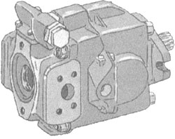
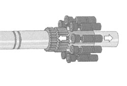
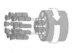
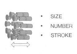
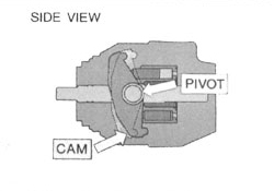
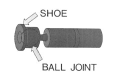
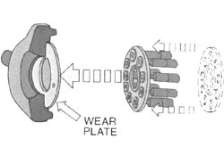
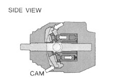
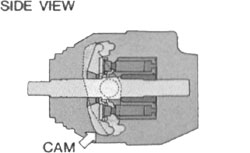
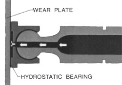
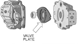
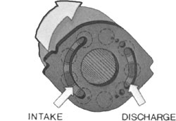
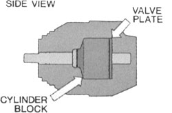
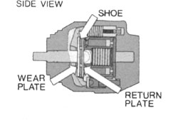
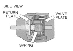
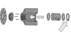
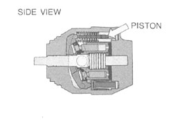
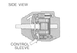
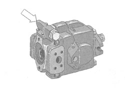
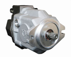
Axial Piston Pumps, Theory of Operation by Delta Q Axial Piston Pumps are highly efficient pumping units capable of high pressures and flows. An axial piston pump with load sense offers flow on demand and with a closed center control valve, little heat is generated when the pump is destroked because no fluid is moved. Fixed displacement pumps must continually pump fluid back to tank through an open center valve. The heat generated even when no load is on the pump represents power loss and higher operating costs for fixed displacement pumps. Because of their superior efficiency, small size and weight, and because of today's increased costs of fuel and energy; axial piston pumps are being more frequently specified in applications once filled by fixed displacement vane or gear pumps. Once axial piston pumps were found primarily in aerospace applications, today these efficient pumps are found everywhere...in large presses, in hydrostatic drives, steering assemblies - all sorts of stationary and mobile applications.
|
||||||||||||||||||||||||||||||||||||||||||||||||||||||||
|
|
||||||||||||||||||||||||||||||||||||||||||||||||||||||||
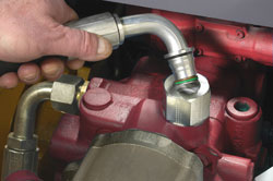 Threadless
connectors make simple, fast, leak-free hydraulic coupling
installations Threadless
connectors make simple, fast, leak-free hydraulic coupling
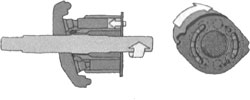
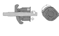
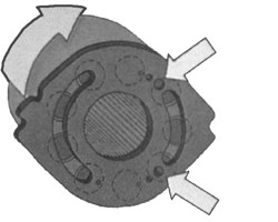
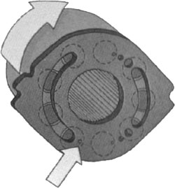
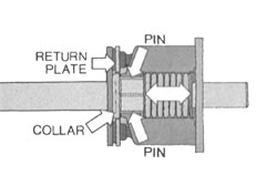
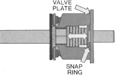
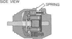
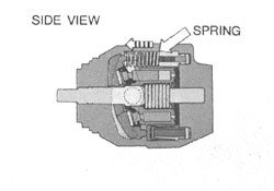
installationsThreadless connectors are an alternative to conventional threaded fittings commonly used in fluid-power systems. The male and female halves simply push together -- without wrenches or special assembly tools -- to form a leak-free connection. Several coupling manufacturers have introduced specially designed threadless fittings that yield the performance of O-ring seals, but eliminate the cost and O-ring assembly problems for fluid power systems with working pressures up to 6,000 psi. These couplings also provide a metal-to-metal seal − like JIC fittings − but they don’t have to be torqued-on to make the connection. These fittings are called quick connect couplings. They are used exclusively at the hydraulic port or manifold on steering units, valve blocks, pumps and motors. For OEMs, they offer several key benefits: - Leak-proof connections that reduce the cost of warranty claims and fluid leaks from equipment used in the environmentally sensitive forestry and agriculture industries, - Easier, quicker connections that result in manufacturing cost savings in the assembly process, - A tactile positive feedback and visual confirmation that the connection has been made, - Assurance that connections cannot be accidentally made with other threadless couplings, - Easy serviceability, and - Easy replacement in the field with traditional and widely available threaded couplings The biggest advantage of threadless couplings is the reduced time and expense needed to install hydraulic hose and tubing assemblies, and the improved accessibility to the hydraulic system. Certain kinds of equipment, such as skid steers, are compact in design and have little room for the plumbing and routing of hydraulic sub-systems, which must be designed into tighter spaces where they are subject to heat build-up and other stresses. Installations with conventional threaded fittings can take several minutes or even hours, and they are subject to leaks because of torquing inconsistencies and other variables. On the other hand, threadless couplings allow even confined, difficult-to-reach connections be completed in minutes. Instead of screwing on the threaded connector and tightening it with a wrench, threadless connecting halves -- the male end and the adapter -- simply push together to form a leak-free connection. A snap ring positively engages the male and female halves, without any assembly tools. Some threadless coupling designs do require a special tool for removal, however. Threadless couplings should be considered for truck/bus, agriculture, construction, material handling, and turf care applications. They are especially suited for quickly making difficult-to-reach, confined-area connections. For additional information about Gates Quick-Lok threadless couplings, contact your Gates Fluid Power division distributor or sales representative. On the Web, go to www.gates.com/quicklok
|
||||||||||||||||||||||||||||||||||||||||||||||||||||||||
|
|
||||||||||||||||||||||||||||||||||||||||||||||||||||||||
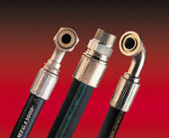 Match
hydraulic system components to ensure leak-free service
life. Match
hydraulic system components to ensure leak-free service
life.Gates Corporation engineers recommend against making a hydraulic assembly with a hose and couplings from different manufacturers. Here’s why. Although most American-made hydraulic hoses, and many imported hoses, are built to confirm to SAE (Society of Automotive Engineers) specifications, the SAE allows a whole range of materials to be used. Hoses from various manufacturers may have comparable dimensions and constructions (SAE), but different rubber compounds and tolerance dimensions (non-SAE). Summarily, each manufacturer designs a coupling to properly fit its own hose manufacturing tolerances. Also, the proliferation of thread ends from around the world in recent years has dramatically increased the possibility of mismatching threads and seats on various couplings. An improperly coupled hose will likely fail (blow off; leakage) causing downtime and possible personal injury. Finally, it's important to: 1) use the crimping equipment of the hose/coupling manufacturer; and 2) always follow the crimp and assembly recommendations of the hose/coupling manufacturer. Each component of a Gates hydraulic system -- application-specific hoses, a full range of couplings and versatile crimpers -- is designed to work together to give you a proven, reliable and safe product. Contact your authorized Gates hydraulic distributor or go to www.gates.com/fluidpower
|
||||||||||||||||||||||||||||||||||||||||||||||||||||||||
|
|
||||||||||||||||||||||||||||||||||||||||||||||||||||||||
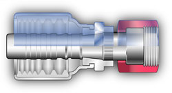 Use
proper torque values when tightening couplings Use
proper torque values when tightening couplingsAn over-tightened hydraulic coupling may be just as apt to leak as an under-tightened coupling. Why? Over-tightening may result in overstressing and/or cracking of the seat or the staked nut. When attaching a coupling, it’s best to use the torque values supplied by the coupling manufacturer. The minimum value will create a leak-proof seal under most conditions. Applying torque values greater than the maximum recommendation will distort or crack the fitting. When tightening couplings, make sure that the hose does not twist on the adapter. Twisting will shorten hose life and scar the sealing surfaces of swivel-type couplings (JIC, 45°, etc.), which can create leaks. For straight couplings, use a torque wrench on the hex-swivel nut and a standard box-wrench on the stem hex. When a crowfoot wrench is used with a torque wrench, adjustments to the torque readings must be made, otherwise over-tightening will occur. By replacing staked- and tube-nut JIC style couplings with Gates Full-Torque Nut™ hydraulic couplings, design engineers can dramatically reduce hydraulic leaks due to over-torquing. For more tips on proper coupling torquing techniques, visit www.gates.com/fulltorque. |
||||||||||||||||||||||||||||||||||||||||||||||||||||||||
|